Monday, August 27, 2012

Single & Tandem Rotor Gyrocopter Thrust Lines & Relative Wind

The horizontal thrust line on a gyrocopter plays a large role in pitch attitude of the platform. If your power plant is mounted to high, your thrust line will be too high above the X axis, causing the nose of the aircraft to pitch downward. This affects the relative wind passing up through the rotor disc, something that gyroplane need. Correcting it requires aft stick input, but only so much can be corrected with control inputs. If the power plant is moutned too low below the X axis, the nose will pitch up. If you are building one from scratch, consult an experienced builder or better yet, a gyrocopter trainer. Microsoft paint is not user friendly, but below I attempted to give some examples.


Below are some altered tandem helicopter that I had intended to be for my patent HIR concept as well, but tweaked to depict a tandem gyroplane. A buddy of mine has been working on a small scale proto of this concept. Like me, he's crashed a few models working through the issues. In conjunction with rotor thrust lines, I had been curious if the geared free wheeling hubs may have a disturbance of air flow with regard to the relative wind. Perhaps the blade tip vortexes disrupt everything...think that's the right term for it. Any way... those little circular flows of air at the tips of the rotor blades. I've seen them when we've popped smoke and the blackhawks flew in to pick all of us grunts up. I'm not an expert, just trying to help a friend trouble shoot.

Ungeared tandem gyroplane. Blades tips have clearence. Relative wind/air columns do not overlap.


Geared, free wheeling tandem rotor gyroplane. Blades pass between one another. Synched, but relative wind columns overlap.


Below was the powered tandem helicopter that I had intended to utlize with the HIR concept. The coaxial works and the single mast almost works.


Below, a couple of pics of Joe Nelson's tandem gyro rigid tethered test jig. The second pic he finally got stable hover. He has had issues with the free flying model with inconsistent rpms between hubs and other issues. He's getting closer to his goal.


Tuesday, August 21, 2012

Martin Jetpack

I've watched the last few years as Glen Martin has gradually moved closer to his goal and has done so with caution and safety in mind. All it takes is one innovative, creative mind and the will to step forward and try.

5,000 feet.


From Martin Jetpack:

Last year the Martin Jetpack flew to 5,000 feet - and parachuted safely down.
If you missed that, check out the video:


Next steps - expanding the flight envelope

Having shown you all that it really does fly, the focus shifted to the disciplined work of expanding the flight envelope - flying faster and in stronger winds.
Latest test flight

The Martin Jetpack is now flying regularly (unmanned) at 50 kph in winds of 15 kph with gusts of up to 10 kph. Check out the latest remote control test flight video:


Manned flight demo

We're planning a great manned flight demo later this year - probably in Auckland. We'll make sure we let you know.
What can the Jetpack be used for?
People sometimes ask what the Jetpack will be used for. As if fun wasn't enough. When Joseph Bombardier developed the snowmobile he thought they would be used by missionaries, trappers and emergency services. Look at where they are used now!

Help us get the Jetpack to market - we need 100 investors

Help us get the Jetpack to market - seeking 100 investors to put in $24,000 each Now we'd like your help to get this to market! Our plan is to release the first manned Jetpack in the middle of 2013 - suitable for search & rescue, police, and other Government services. The personal Jetpack will be about a year later.

We're committed to the
Martin Aircraft Company becoming a publicly listed company. Before we get to a listing later this year or early next year, we're seeking up to 100 investors to put in NZ$24,000 (about US$20,000) each. This will give us the money we need to complete the product and get into the market. It will also give us a good part of the spread of investors we need for a listing. The IPO will be to give us the money to set up production.

To be one of these 100 investors, you need to be an eligible investor under the securities legislation in the country where you live (in the US or NZ this means you have enough money - we can send you the requirements). An allocation of the first personal Jetpacks is being put aside for investors: that is, this is how you jump the queue!

Contact Glenn or Jenny to get your investment underway ... We will send you an Information Memorandum, you subscribe and we have a new partner on our journey!

Happy flying
The Martin Aircraft Company

Glenn Martin, Founder/Director
Tel
+64 (03) 377 8584
Cell +64 (021) 109 1851
Skype: Glennnmartin
glenn.martin@martinaircraft.co.nz


Jenny Morel, Chairman
Cell +64 21 456 086 jenny.morel@martinaircraft.co.nz


Sunday, August 19, 2012

Rotor Hub Review: Alternate Approach Needed? : Schoffmann Home built

There are a few people out there attempting to build their own "Garage Helicopters" and it's good to see all of the creative people working on innovative designs.
One concern that caught my eye is the rigid configuration of the Ivoprop style blade: should it have lead/lag and flapping hinges. If so, given that it is not a rotor blade regarding the rotor chord width and span, would flapping hinges cause too much blade coning and lose lift? It's an intriguing platform.

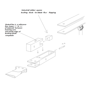
I decided to attempt to design a rotor head that would allow a small amount of flapping action & lead/lag, but without adding excessive weight.
WARNING: Do not attempt to use the following sketches herein on a manned platform. UAS/UAV will require testing. Considerations need to be addressed when scaling up. You are responsible for your on actions and any damage or injuries that may result in not following sound design and fabrication processes. Flying any aircraft, manned or unmanned, can result in injury or death to you and/or others. You are legally, financially, & medically responsible for you on actions. This rotor hub may be sound for /UAVUAS. Keep in mind that allowing the hub to flex/flap in this design will require more distance bewteen the lower and upper hubs when utilized in a UAV/UAS platform if you intend to use the def gear assembly between the hubs to attain counter rotation. Personally I like the idea of two rotor shafts.


This video is the reason for my concern for not having flapping hinges for dealing with dissymmetry of lift. Not a Schoffmann helicopter.


Human Interface Rotor Systems and Morphing Airframes

I wanted to share a few words regarding my interest in HMI (Human Machine Interface). My goal is practical application, so if you're a dooms day follower...sorry I let you down. The human interface software that interests me is none invasive and the idea is to aid operation rather "turn it loose" on it's own and see what happens. Regarding my helicopter designs, for example, should a pilot pass out, the system would notice the unwanted changes in flight control input. I always want a "human in the loop". The only "invasive human interface I think would be ok is that regarding amputees or paralyzed people. They're doing wonderful work to that end and even National Geographic did an article on it.


This effort is not an attempt to replace any UAS. It is simply an update on my approach/effort to civil UAS and manned platforms. I am still not funded by the Army regarding my patent (Pat # 8,226,026 B2) nor is my endeavor to get the platform off of paper and into the air. But, I'm still going to keep "plugging" away on my own. The designs that I've given to the Army/DOD are separate. Further I have nothing to do with any military rotorcraft/aerospace programs outside of the designs that were given.
I finally made head way in getting the 2nd coaxial HIR prototype into the air with fairly good control for the first hop flight. No swash plate.
Some of you may be thinking it resembles the Japanese GEN H4 or the Airscooter coaxial systems, but those respective airframes, though innovative, are simply tilt mast and both airframes are fixed pitch. Now, my small scale coaxial is also fixed pitch, but it's not simply "tilt mast". It is two airframes that are interconnected with the upper airframe containing the rotor system, tilting independently from the lower airframe, thereby allowing for the application of full collective pitch and yet the weight remains equally distributed between both airframes. If the upper airframe tilts forward, the rotor thrust is vectored as well as the lower portion of the upper airframe that interconnects with the lower airframe via a longitudinal lever/airframe strut, moves aft, but at equal moments, "flexing" the CG rather than a lateral or linear shift in weight within the airframe. A sort of "pendulum" flex, if you will. My theory.

If you review the video clips of the GEN H4 flying, the operator appears to have a "cautious" hold on the control stick that tilts the power plants and masts, but it appears too "loose" as if it may be more easily to over correct, but I cannot be certain. It appears not to be intuitive. With "planform" morphing/HIR airframes, the control stick manipulates both airframes, but not in a "stick to the rotor discs" manner. Connecting the weight of both airframes together, to include the pilot weight in a manned platform, adjusts the the attitude of the upper airframe/masts for direction control. Should any atmospheric gusts hit the rotor discs, it will be translated into both airframes, pilot weight, and then to the control stick. That translation from the rotor discs is "buffered". Further, there may be better control feedback to the operator. With the GEN H4, an atmospheric gust would seem to translate straight to the control stick as the rotor masts/power plants ride on a single gimbal. My platform will use a gimbal as well, but there are always two attachment points between the two airframes with the control stick controlling movement between the two. The GEN H4 has one attachment point between the rotor discs and lower airframe. Two if you count the pilot's hand on the control stick. Now, I need to get the 1st single mast prototype flying. The airscooter again is fixed pitch. Further, it utilizes both a dif. gear system and a polychain pulley system.
Later this week, I will move outdoors and attempt maneuvering around obstacles. Last year, my original plan was to include some sort of "SMART" software that will assist in keeping the airframe in the most optimal configuration for translational flight. If you can remember learning to ride a bicycle and Mom or Dad kept their hand on the seat as you peddled away until you internalized the balance required and then they would let go of the seat. SMART software that can sense pilot control inputs and then make a decision of whether or not to adjust stick control input or take over. But, as of right now, my airframe is only a physical human interface regarding the weight of the pilot moving, interacting and assisting the airframe configuration in control of the platform/thrust vectoring during flight. Time will tell.


Outdoor Flight

I'm still not satisfied. Made some changes, 180 degree flip on the forward/aft servo, but no a cherping has developed, causing inconsistent rpms and excessive yaw that neither the trim tab or yaw control surface can counter. The concept works, so I'm scaling up to gas powered. I have a 54 cc chain saw engine and I intend to use a go pro camera.


Airframe hit the ground from 15 feet....airframe was more rugged than I had expected. The combination adhesive with carbon fiber gusset plates was a good choice on my part. The battery/yaw control platform broke free. It still flew, but lost forward/aft control which I expected. Regarding planform morphing airframes, if there are not 2 points of connection with the weight equally distributed between both airframes, allowing both airframes to move within "one another" the lower airframe will act like a clock pendulum. I suppose my theory proved right.


Airframe detail below

http://www.youtube.com/watch?v=PKixR_89BQg


Sunday, August 12, 2012

Finally got the 2nd prototype helicopter of my patent up and flying; no swashplate; planform morphing airframe rotor disc control. I still need to tweak the yaw control and increase the surface area of the yaw paddle. I added a small washer w/ some teflon grease between the reduction gears, but it may be causing a little friction, slowing one of the mast down and causing excessive yaw, but it can be negated with additional yaw control input to counter it. More tweaking and I can move outdoors now. Now to get the boom and pod single mast platform flying.


Friday, August 10, 2012

Coaxial Prototype of HIR

The 2nd coaxial prototype of my patent flew, but the CG is off. It drifts aft and to the left. Further I need to cut some weight on the airframe.http://www.youtube.com/watch?v=gzYRF9xLs9s