Over the past few years, I have noticed that larger industries and groups that "pool" multiple industries and others in different fields of business/technology, have demonstrated poor business etiquette when dealing with people who are independents as well as those who have a firm footing in their respective technological fields, but are still considered "small entity". Change 1: Out of courtesy, I removed the names of the respective industries that have questionable etiquette and/or integrity. Pointing fingers will never change anything. Further, change would need to come from within any organization. Poor etiquette and integrity are simply the result of poor leadership in part or as a whole within any organization. The cliche' phrase "it's only business" is foolish to use in an attempt to justify having a lack of integrity.
All are treated in a similar manner. So why is it that the larger icons of respective industries deal with everyone in this "business caliber" this way? Big industries have the resources, time and legal backing to keep smaller entities tied up in a legal "merry-go-round" for a long time. Some even circumnavigate patent laws to infringe the rights of intellectual property held by small entities and independents. It's difficult to understand why a company would utilize methods of poor integrity to gain control of intellectual property, but it happens more often than people think. Large industries will spend thousands upon thousands of dollars to have academia institutions study a technological field, but when present with a concept that may/may not advance any given state-of-the-art technology, they resort to "short handed dealings", spend more money tangling it up in their legal department to keep independents at bay, when much less money would be spent just buying the patent rights out right. Most independents spend years refining one concept of technology that they wish to present to larger industry in hopes of having some sort of monetary gain. However, not all of us pursue our endeavors this way. I consider myself as "unselfish" when sharing ideas and I have no desire to "toot my own horn". I cannot give all ideas away, but I have shared more than a few ideas between respective industries, DARPA, and the military. Some on the side of DARPA & the military still deal in a manner that is "less than desirable". I was never concerned about getting "credit", but a little feedback would have been appreciated. I will continue to offer ideas when allowed to do so because for myself and my peers.... we're the "end state" user of what all of industry puts out and should have been the end state user of what industry failed to put out. So remember that your "politics" had an effect on us on the ground in Iraq, and will continue to effect us on the ground in Afghanistan and future fields of war. Good or bad, you as a member of industry have a hand in our support or our demise.
No one can say that those respective big industries are not professioanl regarding their fields of technology. This post simply questions why the poor etiquette?
http://www.rotorwashinternational.com/forum/index.php?topic=850.msg1908#msg1908

Simply a link for VTOL and similar rotorcraft, but mostly unproven and proven designs with a particular interest in morphing aero-structures and Human-machine interface.
Friday, December 28, 2012
Sunday, November 25, 2012
Advancement in Rotor Systems and Smart Rotor Systems
Here's a link that I found with it's origins in Canada. Aside from DARPA and a few otheres, there is a great deal of interest in "SMART" systems when regarding rotorcraft control. "SMART" and/or adaptive control is the last piece that I would like to implement into my rotor system. The Human Interface Rotor System outlined in my patent is only a physical interface regarding the pilot weight being distributed between the two planform morphing airframes and facilitaing rotor disc attitude. That final piece of utilizing SMART software to allow real time monitoring of flight control input & assist with manipulation when needed is the final goal and will bring the human interface, with regard to my airframe, to a full circle.
D. Hickman
http://www.smartrotorsystems.ca/
D. Hickman
http://www.smartrotorsystems.ca/
Tuesday, October 23, 2012
Stuff about Arrow Gear Company
A few pics regarding Arrow Gear. They do heat treat. All ring gears are carburized and die quenched.


Sunday, October 7, 2012
Weight Shift- CG Manipulation Rotorcraft Control
Photos coutesy of Steve Remington, Collect Air: All photos fall under the respective copyrights of either Collect Air, Cessna, and/or Seibel Helicopters. No copyright infringement was intended with this posting. All due credit goes to one or more of the above mentioned entities.
http://www.collectair.com/cessna.html
There have been a number of perspectives with regard to weight shifting control for rotorcraft/helicopters and even more concepts designed, patented, and attempted. Some successful and some not.
One in particular is a design by Charles Seibel. Seibel, a left field pioneer with respect to rotary wing aircraft, refused to let the "main stream" prevent him from building his platforms. Even when they laughed at him.

Seibel pushed forward and started to build his rotorcraft in his attic while working for Bell in New York and finally in his basement when he moved to Kansas. Using Ford motor parts and scraps of aluminum, he built the S-3 in three different segments so it could be removed easily. What was most intriguing to me was when it came time to test the helicopter, Seibel fly it himself, though he had no license and no flying experience.
Seibel's design used weight shifting in the the form of moving the pilot's cabin forward, aft, and laterally thereby changing the CG, causing the helicopter to move in that direction.


http://www.collectair.com/cessna.html
There have been a number of perspectives with regard to weight shifting control for rotorcraft/helicopters and even more concepts designed, patented, and attempted. Some successful and some not.
One in particular is a design by Charles Seibel. Seibel, a left field pioneer with respect to rotary wing aircraft, refused to let the "main stream" prevent him from building his platforms. Even when they laughed at him.
Seibel's design used weight shifting in the the form of moving the pilot's cabin forward, aft, and laterally thereby changing the CG, causing the helicopter to move in that direction.

S-3 Moveable Cabin/Weight Shifting Control

S-3 with Cyclic Control
Though the S-3 with weight shifting could fly and be controlled, it would at times tend to want to roll over in the event of a hard landing as outlined in the Collect Air web site. I believe that is the purpose for the lateral extending struts seen in the first S-3 photo above.
The HIR design/patent, a 15 year old idea that I brought off of the back burner, started to take shape in 2005 in simple sketches. After I ran across the Collect Air web site, I thought perhaps that I was not crazy. Though my design was not a "linear" shift in weight like that of Seibel's design, could it still fly? Seibel's platform flew. After viewing the fixed pitch restrictions of both the Airscooter and GEN H-4 helicopters, I designed the HIR platform to utilize two separate airframes that worked "within" one another, incorporating the weight of the pilot which remains distributed equally between both airframes and with the added ability to tilt and reconfigure the airframes at will to vector the rotor disc thrust, yet all at equal moments and spans of motion. I must admit that the final draft was a result of attempting to solve a chain of set backs. I wanted a tilt mast helicopter, but then how would I prevent binding of push/pull rods or tubes, i.e. maintaining collective pitch? Further, if the mast tilted, how would I keep continuous power to the tail rotor? These two problems led me to design the morphing airframes, which then led to having to solve the unintentional collective pitch change as the airframes change configuration. That led to my designing it with a canted collective pitch stick.
There will be further trouble shooting and there are still hurdles to clear before I am satisfied. The trick is to find and learned the parts of physics and mathematics that are not yet known with respect to this concept of rotorcraft
Friday, September 28, 2012
Morphing Airframe Rotorcraft: What is the Extent of the Platform Practical Application
I'm still in the "walk phase" with this design. I'm satisfied that the concept works, but as with anything that I put my effort into, how far can I push it? Still yet, I always question myself: Where does practical application end and novelty begin? That being said, how can this platform be applied to what is considered the "norm" with respect to what is required for helicopter capabilities today?
What's expected of a helicopter or rotorcraft:
- performance with repsect to all weather conditions for both military and law enforcement operations.
- distance and endurance with respect to operational cost per hour, etc.
- Sling load operations. This has been in the back of my mind and continues to be a pressing thought for me. I will start small scale sling load testing within the next year. Can a morphing airframe helicopter safetly lift and carry sling loaded cargo? How will said cargo effect the control considering that the weight of the two airframes is equally distributed for control....ie, excessive stick feedback?
I'll have other comments as I get further along. There are many consideration when scaling up.
The sketches below are crude drawings that I put together a couple of years ago. The HIR airframe can be applied to forward and aft flight, but a "partial" swashplate control input may need to be added. Pitch control would be mast internal and an additional "rotor prop" will need to be added to the hub for lateral flight control, but lateral control input must not effect main rotor blade pitch. I still want to avoid the angular differences between retreating and advancing blades.


Tuesday, September 11, 2012
Major General Crosby on the DOD Rotorcraft Modernization Programs
Well, let's see the cancelled the RAH-66 Commmanche...let's see how far this goes!
RECORD VERSION STATEMENT BY
MAJOR GENERAL WILLIAM T. CROSBY
PROGRAM EXECUTIVE OFFICER, AVIATION
BEFORE THE
SUBCOMMITTEE ON TACTICAL AIR AND LAND FORCES
COMMITTEE ON ARMED SERVICES
UNITED STATES HOUSE OF REPRESENTATIVES
ON DEPARTMENT OF DEFENSE ROTORCRAFT MODERNIZATION PROGRAMS
SECOND SESSION, 112TH CONGRESS
MARCH 27, 2012
NOT FOR PUBLICATION UNTIL RELEASED BY THE
COMMITTEE ON ARMED SERVICES
2
Chairman Bartlett, Representative Reyes, distinguished Members of the Subcommittee on Air and Land Forces and distinguished members of the subcommittee, I am pleased to be here today to discuss Army Aviation Modernization. I welcome this opportunity to testify before you and appreciate the tremendous and ongoing support this committee has provided to our Army and our Soldiers stationed around the world. I know you all will agree that our Soldiers have performed magnificently and our families have sacrificed much for our nation over the past ten years.
After a decade of continuous deployment and the associated stress and strain on the Army and its assigned weapon systems, and as the Army’s operational posture changes, we have assessed our current situation to ensure the correct strategy is in place to successfully overcome current and future challenges.
Today we are faced with uncertain strategic and operational environments coupled with declining resources. The Army’s Aviation Modernization strategy reflects the need to be able to support the current fight, set priorities, make prudent choices, and continue to modernize our Army Aviation systems in ways that provide the best force for our Nation within the resources available. We recognize that this is a tough time for our nation and share in the economic responsibility of finding new and innovative ways of acquiring and sustaining our Army Aviation weapon systems smarter, faster, more affordably and more effectively. We realize that we must take an appetite suppressant as we bridge that gap and take calculated risks in some areas.
In taking some of those risks, we also have to make sure that the impact on our Soldiers is minimal. We will adapt to the current budget realignments the best way we can and maintain an open line to our deployed forces and combat commanders. As such, we continue to modernize our airframes and tackle obsolescence and sustainment challenges. Long term sustainment is key to the logistical support of our aviation platforms.
As the Army’s materiel developer of Army aircraft and weapon systems, the Program Executive Office for Aviation has taken a proactive approach to our Aviation Modernization Plan that ensures a balanced, long range approach. We recognize that
3
we must adapt our plan while avoiding the natural tendency to cut our investment programs to meet short term mandates. Our plan accepts risk in some modification improvements, minimizes the impacts to our industrial base by preserving our multi-year contracts, and extends the production plan by three to five years in the long term (reducing quantities in the near-term). This was done to preserve our Science & Technology (S&T) investments in a future vertical lift, maintain our path to address the deficiencies in the Scout mission area, and continue our procurement and modernization of our current platforms and our Unmanned Aircraft Systems (UAS).
Further, strategies to develop Future Vertical Lift (FVL) while sustaining the current fleet and accepting a level of risk in some current mission areas have to be considered in a balanced approach. Future Vertical Lift will have to be scalable within available resources with priority given to the utility and attack fleet.
In continuing support to our Soldiers, the latest generation of Apache, the AH-64D Longbow Apache Block III, will enter service this year. We are continuing our commitment to maintain the Apache fleet as the world’s premier attack helicopter with our modernization strategy. The new Apaches are stronger, faster and much less constrained in extreme combat conditions. Improvements include an enhanced digital electronic engine control unit, which improves the responsiveness of the rotorcraft’s twin GE T700-701D engines, along with composite main rotor blades and more powerful computer systems that even allow pilots to remotely fly unmanned aircraft. Our current Block III procurement objective will be 634 remanufactures and 56 new builds. The program is currently undergoing Initial Operational Test & Evaluation at the National Training Center in Fort Irwin, California. Modernization focus areas include the overall Block III program, an advanced crew station, advanced sensors and Aviation Survivability Equipment (ASE), advanced weapons, and improvements to the platform and sustainment. The Army is planning a multi-year contract with the Apache Block III program after a full rate production decision.
Unmanned Aircraft Systems (UAS) continues to be a capability in high demand, and we continue to respond to requests from theater for additional UAS assets. We are currently supporting a significant Raven small UAS surge effort, doubling Raven assets in Afghanistan. We are gearing up for the Gray Eagle Initial
4
Operational Test & Evaluation this year, and this crucial milestone will pave the way for moving that key system into full rate production. Preparations are already being made for Manned Unmanned Systems Integration Capability (MUSIC) Exercise 2 after a very successful demonstration of the first MUSIC event at Dugway Proving Ground, Utah last September. The exercise showcased many of the advancements in interoperability and the manned-unmanned teaming community. It set the stage for future interoperability improvements to benefit our Army’s deployed forces.
We recognize that in some geographic locations, such as Afghanistan, circumstances dictate the need for Vertical Takeoff and Landing (VTOL) capabilities. While the Shadow, with its highly accurate and sustainable Reconnaissance, Surveillance and Target Acquisition (RSTA) capability, continues to provide an integral asset to the ground commanders’ battlefield awareness, there are distinct advantages to having VTOL capability in remote and difficult terrain. VTOL capability would also provide a closer match in capability between the manned and unmanned systems to expand the Soldiers’ options in teaming operations. The Army is dedicated to the VTOL capability, and we are working on the deployment of three Army ARGUS A160s (AAA) to Afghanistan this summer as part of a Quick Reaction Capability.
The next generation of UAS will be marked with three capability focus areas: greater flexibility to the user, superior capability, and advanced autonomy. They will be network resident, enabling the UAS to be responsive to networked commands and broader more force pervasive requests for Reconnaissance, Surveillance and Target Acquisition and Intelligence, Surveillance and Reconnaissance (ISR), and capable of optimizing planning and usage. Current generation single payload, single sensing modularity platforms will give way to multi-spectrum, multi-sensor platforms capable of finding targets down to dismount and IED size efficiently and effectively. Lastly, those systems will have increased intelligence and autonomy on the vehicle systems to improve on the capability per person force structure. In other words, we’re going to do more processing on the platforms to allow for less post-processing, exploitation and dissemination.
5
Our most current pioneering effort in UAS is the development of the Ground Based Sense and Avoid (GBSAA) system. Over the past decade, UAS have become an integral part of the United States military. However, a significant challenge hindering the ability of the U.S. military to operate, to test, and to train UAS in the U.S. National Airspace System (NAS), is the inability to comply with Federal Aviation Regulations which require the ability to “see and avoid other aircraft.” Manned aircraft see and avoid routinely, but with no pilot in the cockpit, UAS must develop an alternate means of compliance to this requirement in order to achieve the ultimate goal of routine and unfettered access to the NAS and ultimately to international airspace, which is required to maintain strategic overwatch through worldwide force protection of our UAS. Developing and validating a technological capability to “sense and avoid” will satisfy this alternate means of compliance. Significant effort and accomplishments in the development of GBSAA, as a practical solution to gain initial access to the NAS, have resulted in GBSAA providing an impending and immediate solution with significant promise to incrementally improve and ultimately be an element of the final integrated NAS access solution for UAS. The final solution involves integration with Airborne Sense and Avoid (ABSAA) systems. Current funding requirements will further support data collection, data analysis, safety case development, equipment procurement, and testing. Additionally, funding would provide the ability to research and develop new technologies to support incremental improvements of the system, which will ultimately allow unfettered and unrestricted airspace integration of UAS into the NAS. A need exists for a reconfigurable and deployable system, which could be utilized in a variety of other ways including U.S. border patrol and a capability to respond to national emergencies. A deployable GBSAA system would enable UAS to fly side-by-side with manned platforms using this deployable GBSAA system as the operator’s eyes in the sky.
Army Aviation OPTEMPO at its highest point ever and the Chinook is the rotary wing aircraft of choice in the OEF theatre. We are continuing to field the CH-47F Chinook helicopters to our units, and our tenth delivery this April will be to the 16th Combat Aviation Brigade (CAB) in Alaska. The CH-47F features an all new machined airframe, with a common avionics architecture system cockpit that meets all future force
6
digitized interoperability requirements, full authority digital automatic flight controls system, among many other integrated improvements. A follow on CH-47F Improved Cargo Helicopter multiyear contract (FY13-17) will allow the Army to complete modernization of its legacy Army National Guard/Army Reserve CH-47D Chinook Fleet with a 10.1% savings (~$373 Million) in procurement cost. With 83% of the Army’s Chinook fleet originally manufactured in the 1960s, replacing these aircraft at a reduced procurement cost is a prudent course of action. We have also streamlined the modernization process and charged one product office to manage all modernization efforts for the Chinook helicopter fleet such as replacing the floor with an integrated roller system, implementation of Condition Based Maintenance tools, development of advanced rotor blade configuration, avionics upgrades, hostile fire detection and other protection systems. The Cargo On/Off Load System (COOLS) replaces the current floor on the CH-47F, and significantly reduces the workload for aircrews and allows rapid, in flight re-configuration to support a wide range of missions. Flight testing will take place Summer 2012 and these COOLS kits will be fielded to units to support upcoming deployments. The full rate production decision will be made in the 1st quarter, FY13. The Army celebrated the Chinook’s 50th anniversary last September, exactly 50 years since the Chinook’s first flight. This milestone speaks volumes about the aircraft’s proven relevance and capabilities as the Army’s only heavy lift helicopter and continues to be vital to Overseas Contingency Operations (OCO) and our nation’s Homeland Security needs.
Modernization efforts of the Army’s Utility UH-60M helicopters continue and are focused on three specific efforts: our continuous modernization of the UH/HH-60M fleet, the digitization of the UH-60L cockpit, and completing the development and testing of fly-by-wire (FBW) technology this year. Currently, 331 UH-60Ms and 93 HH60Ms have been delivered so far. The UH-60M provides extensive capability beyond the legacy UH-60A/L platforms in that it provides a fully integrated glass cockpit that improves situational awareness and reduces operator work load in a complex combat environment through digital moving map displays, multi-band radio systems and improved aircraft survivability equipment. The system's reliability, availability and maintainability have also evolved with the integration of a real-time vehicle health
7
management system reducing overall maintenance and sustainment costs. The Army’s current procurement objective for the UH-60M Baseline is 1,367 aircraft. To preserve our multi-years with this system, the Army plans to reduce the number of UH-60Ms purchased in FY14-18 and extend the planned procurement through FY26. The Army has incorporated the flexibility to procure lower annual quantities in the new multi-year contract currently in negotiation.
Production of our UH-72A Lakotas remains on schedule and cost with 209 of 345 delivered to the Army. Serving as the Army’s newest helicopter, the Lakota supports our Active Army and National Guard missions. The Security & Support Battalion Mission Equipment Package (S&S MEP), the latest LUH configuration adds an Electro-Optical / Infra-red Sensor, a searchlight, and data collection, display and downlink systems and supports counter-drug, law enforcement, border patrol, and Homeland Security missions across the U.S., Hawaii and in Puerto Rico. The LUH program has been touted as a model acquisition program throughout the Army.
Under the Utility Helicopters Project Office, effort is also underway on the Improved Turbine Engine Program (ITEP) which will develop the next generation engine bringing reduced fuel usage, increased performance, improved reliability and lower maintenance. It’s use will provide significant fuel savings for current UH-60 Black Hawks and AH-64 Apaches with a reduction in cost of operations and dependence on oil, improvement in range, endurance and on-station (loiter) aircraft capability, and will save lives now lost moving and protecting fuel on the battlefield and lightens the logistics load. Leveraging today’s ITEP investment will provide Future Vertical Lift platforms with significantly increased capabilities that will meet the warfighters’ unique mission requirements. This translates to a 25% specific fuel consumption decrease, 35% production and maintenance cost decrease and will incorporate a Condition Based Maintenance plus (CBM+) package, 65% horsepower to weight increase with 20% engine life design increase. Engine level demonstrations are slated to begin in FY12. Our current procurement plan is to have Low Rate Initial Production in FY19. The ITEP is also aligned with the Army Operational Power and Energy Strategy, the DoD Operational Energy Strategy, and the National Defense Strategy.
8
The Army is undertaking key modernization efforts in the Project Office for Aviation Systems that include Automated Aviation Logistics (AAL) and Degraded Visual Environment (DVE). AAL will replace the Unit Level Logistics System-Aviation (Enhanced) and the Unmanned Aircraft Systems-Initiative (UAS-I) with a best of breed, state of the art family of systems for all manned and unmanned aircraft in both conventional and special operations tactical units. The end result will be game changing capabilities for net-centric Aviation maintenance, supply, operations, safety, training, and readiness information in both connected and disconnected environments; seamless interfaces to the Global Combat Support System-Army (GCSS-Army) & the logistics enterprise; and elimination of today’s knowledge gaps which force commanders and maintainers to make decisions based on incomplete and anecdotal information. AAL’s Aircraft Notebook (ACN), Aviation Data Exploitation Capability (ADEC), and Aviation Logistics Enterprise-Platform (ALE-P) are scheduled to begin fielding in FY14 in concert with GCSS-Army.
Degraded Visual Environment (DVE) is an effort to mature and acquire obscurant penetration sensor technologies for rotary wing flight operations. Army aircrews often encounter flight conditions that severely restrict the flight crews’ visibility due to brownout, whiteout, or other natural or manmade atmospheric obscurants. DVE technologies will provide aircrews with real-time visual information of the terrain and obstacles encountered during combat and training flight operations. Potential DVE solutions may include a combination of both active and passive sensor technologies, enhanced flight control systems, and the integration of flight symbology. The integration of obscurant penetrating technologies on the Army’s rotary wing fleet will both save lives and resources while increasing combat capabilities.
Army Aviation Aircraft Survivability Equipment (ASE) modernization efforts continue to focus on detecting and defeating highly proliferated Man-portable Air Defense Systems (MANPADS) and small arms munitions, the greatest threats to the preponderance of the Army Aviation fleet. The Common Missile Warning System (CMWS) detects infrared-seeking missiles and protects aircrews and passengers by employing expendable countermeasures. CMWS is also being upgraded to detect unguided small arms fire to provide better threat situational understanding to Army
9
aircrews. The Advanced Threat Infrared Countermeasures (ATIRCM) system provides laser-based countermeasure protection to select aircraft deployed in Afghanistan and the Common Infrared Countermeasures (CIRCM) system will provide laser-based countermeasure protection to the greater Army Aviation fleet as well as US Marine Corps assault platforms. As the National Military Strategy shifts focus to the Asia-Pacific Theater, the Army is readdressing the significant capability gap against Radio Frequency (RF)-guided threats. These multiple ASE modernization efforts are being integrated to optimize aircrew situational understanding and enable off-boarding of geo-located threat data to inform route planning and operational commanders.
Any further funding decrements to ASE programs will jeopardize aircrew and passenger survivability against IR-seeking missiles and small arms fire. While the Army has no procurement for a new Radar Warning Receiver (RWR), the ASE program office is seeking to leverage US Navy RWR modernization efforts with limited Army RDTE funds to replace the current RWR, which is wholly inadequate for employment in the RF threat-heavy Asia-Pacific Theater. Further funding cuts would also hamper efforts to integrate ASE to provide comprehensive threat situational understanding, coordinated countermeasures, and off-boarding of geo-located threat data to air and ground operational commanders.
The Army senior leadership recognized the magnitude of work required to acquire, field, sustain, and modernize the Army’s Fixed Wing fleet and on October 2011, we stood up our newest Project Office for Fixed Wing aircraft. This office is pursuing several aircraft acquisitions, some of which includes the modification of six new C12V1’s (Hawker Beech B-200 series aircraft) with the latest military communications, navigation, surveillance, and aircraft survivability equipment for worldwide deployability. There is also ongoing procurement to provide the Golden Knights with three new Twin Otter 400 aircraft to support their recruiting and parachute demonstration missions. While working to acquire new aircraft and retire the Army’s older fleet models, the office will perform a series of modifications to ensure the Army’s current fleet continues to operate in accordance with all civil and military requirements.
10
The venerable OH-58D Kiowa Warrior has been maxed out over the years and continues to be the aircraft of choice with our ground commanders as well as the aircraft with the highest op-tempo. We continue to push capability improvements to the field to address Operational Needs, reduce aircraft weight, enhance maintainability, improve safety, and address obsolescence and weight reduction, part of which is the Cockpit and Sensor Upgrade Program (CASUP)/OH-58F initiative.
CASUP is designed to address avionics obsolescence inherent to an aircraft that has not undergone a comprehensive, modernization effort since the designation modification from the unarmed OH-58D Army Helicopter Improvement Program (AHIP) to the armed OH-58D Kiowa Warrior in 1990. Obsolescence will be addressed through modernization interoperability, Aircraft Survivability Equipment (ASE), armament and lethality, sensors, digital cockpit display/ processor/controls, navigation guidance, and communication / identification. CASUP’s capability increase is largely centered on the Nose-Mounted Sensor (NMS), which will replace the current, and obsolete, Mast-Mounted Sensor (MMS). Additionally, CASUP will fully integrate several aircraft systems that are currently federated, redesign and replace the entire aircraft wiring harness, and add a capability to integrate future digital weapons systems. CASUP/OH-58F First Unit Equipped (FUE) is scheduled for 2016 and will modify all OH-58D aircraft to the new configuration. Work began on the first series of production and engineering aircraft in spring 2011. Pre-flight, ground test runs are scheduled in summer 2012, with First Flight of the CASUP/OH-58F configuration occurring in early 2013. The Army plans to convert all OH-58D aircraft to the OH-58F configuration through the CASUP production line. Squadron fieldings will take place from FY16 through FY21.
Fielded fleet upgrade efforts are on going to reduce weight, address obsolescence, improve reliability, and increasing capability. These efforts include: Manned-Unmanned Teaming (MUM-T) which allows the OH-58D to view video from UAS and other aircraft in real time; analyzing options for the .50 Cal Machine Gun to provides a more reliable weapon system over the existing M3P gun; Lightweight Floor Armor which increases the safety of the aircrews; the Common Missile Warning System (CMWS) which increases the aircraft and crew's survivability against surface-to-air threats; and the Health and Usage Monitoring System (HUMS) which increases safety and
11
reliability through the monitoring of critical aircraft systems and components. The Army is fielding the reduced weight missile launcher, the composite weapons pylon, and the light weight multi-function displays. In addition, the Army is fielding the single channel Full Authority Digital Engine Control (FADEC) to address safety. The OH-58D continues to maintain the highest operational tempo of any Army Aviation asset.
An analysis of alternatives (AoA) validated the need for manned reconnaissance and recognized the benefit of Manned/Unmanned Teaming as it applies to closing the capability gaps we believe we will see in the future. The analysis clearly states that the only way to completely address those gaps is with a new-start aircraft development program. Our assessment is that a new-start program is too costly.
As we look to the Kiowa Warrior future and bridge to the Armed Aerial Scout (AAS), we look to ourselves and ask, what is that new capability? With the current budget environment, there is no way we are going to be able to implement all the new capabilities for the future of the entire aviation fleet plus a new start AAS right now. So we have developed a strategy that states: take risk in the scout area and focus on that new Future Vertical Lift (FVL) capability down the road with an Aim Point of 2030.
Our path forward with the AAS does not involve a fly-off, but rather a demonstration which will enable us to make an informed decision on a path ahead and to find a materiel solution to replace or extend the current fleet of our aging OH-58D Kiowa Warrior helicopters. The AAS demo will clearly define whether we execute a Service Life Extension Program (SLEP) of the OH-58 aircraft, consistent with what we have done to the other platforms, or if we pursue an alternative material solution option that represents a medium risk program with achievable and affordable requirements within the current and future fiscal environment.
The funding is in place, awaiting approval to execute the demonstration from the Defense Acquisition Executive. The proposed April 2012 demonstration schedule was based on receiving authorization NLT December 2011. Since authorization was not provided in December 2011, the schedule has shifted to late spring/early summer depending upon the date authorization is received. A draft Acquisition Decision Memorandum (ADM) has been written and is currently being reviewed with OSD AT&L.
12
Upon receipt of the revised ADM, the Request for Information (RFI) will be released to industry and will include a timeline for submission of written RFI responses and execution of the demonstration. It is anticipated that the slip will not impact the position in the POM but the decision point for the Army. The Army will continue to execute the current programs (CASUP and planning for a Service Life Extension Program) at their resourced levels until such a time a decision is made by the Army. If the determination offers an affordable and capable alternative, resourcing of the resultant program will be accomplished using existing program funds within the aviation portfolio. The Analysis of Alternatives recommended the AAS be capable of hovering at 6,000 feet above ground level at 95 degrees Fahrenheit Hover Out of Ground Effect (HOGE) (“High/Hot”); 550 KM Range; one hour station time at 212 KM; and 135 knots Airspeed.
As the budgets come down, we recognize that it will be difficult to resource Army Aviation at the same level in the future. We continue to successfully modify, upgrade, and remanufacture current existing platforms to extend the life of our aircraft and keep our aircrews safe. Even with all of the great work we are doing upgrading and supporting the current fleet, now is the time to invest in the S&T required to develop the future fleet. We are still flying third generation vertical lift platforms designed during the Vietnam War era, nearly 50 years ago. Our current fleet will not last forever and there are bounds to our ability to upgrade current designs to meet future needs. The requirement for vertical lift will not decrease in the current or future military engagements compounded at times with extensive humanitarian assistance and disaster relief efforts.
Army Aviation is part of an early stage Science and Technology effort by the Pentagon and the U.S. Army to engineer, build and deliver a next-generation helicopter with vastly improved avionics, electronics, range, speed, propulsion, survivability, operating density altitudes and payload capacity. The Army-led Joint Future Vertical Lift (JFVL) program is a broadly-scoped Pentagon effort, including input, officials and working group members from OSD, other military services, Coast Guard, Special Operations Command and NASA, among others.
The focus of JFVL is to get at the three major tenets: improve the performance, improve the survivability and significantly reduce the operating cost. While the JFVL
13
program includes the exploration of light, medium and heavy lift helicopter variants, the effort will initially focus on medium lift options. The next-generation aircraft will have to be a whole lot less expensive to operate than the current fleet.
Building a new aircraft from the ground up is part of an overall strategic effort to harness the best new technologies, allow for the platform to be upgraded as new technologies emerge, integrate systems into a common architecture and, perhaps most of all, drive down costs. Affordability is the utmost priority with the JFVL effort.
Development and fielding of the next-generation family of aircraft depends on the capabilities of the U.S. technology base to design, mature, deliver, and sustain these aircraft. U.S. vertical lift industry members, using independent research and development funding, can aid technology development in this sector. This initiative provides uncommon unity of effort and focus of both DoD and industry, reducing redundancy and collaborating on identified areas of greatest need. The publication of the DoD Strategic Plan for Future Vertical Lift Aircraft focuses on resources on high-priority areas.
Since the delivery of the Report to Congress, significant and concrete activities continue to evolve. The Army, as the lead service for this Joint effort, is heading the development of a Joint Initial Capabilities Document with a target release date of spring 2012 for staffing. This effort is informed by a design tradeoff analysis being conducted by a Joint team of DoD aircraft preliminary designers.
To complement the DoD concept design effort, the Army has awarded four concept trades and analysis (CT&A) contracts to Boeing, Sikorsky Aircraft, the Bell-Boeing Team, and the AVX Aircraft Co. These four efforts will perform design trades using the same set of attributes as those used by the DoD team, to ensure that both industry and the government understand the potential solution space to address the capability gaps identified in the Capabilities-Based Assessment (CBA) process.
In addition, the Army has focused its Aviation S&T effort toward a Joint Vertical Lift Technology Demonstrator program, with plans to develop two flying demonstrators for first flights in the 2017 timeframe. This involves a major funding commitment for Aviation S&T. At the end of the CT&A phase, contracts will be awarded to build actual
14
flying demonstrator platforms to mature the critical technology enablers defined during the CT&A effort.
These will be the first DoD vertical lift demonstrators developed since the Army/NASA XV-15 in 1977. A similar effort, focused on the mission systems for the next-generation vertical lift platforms, is being defined for initiation in FY12. Mission equipment demonstrators will be integrated into the platform demonstrators, with a targeted first flight of the complete demonstrator air vehicle in the FY19 timeframe.
Finally, the Army’s Program Executive Office (PEO) Aviation and the Navy’s PEO Air ASW, Assault and Special Mission Programs are collaborating to develop an acquisition strategy for a potential new, joint program to develop and field the next generation of vertical lift aviation in the 2030 timeframe. Future Vertical Lift aircraft is an integral part of our long range plan and part of our balanced approach to maintain our investments. 2030 is the aim point for a new system to replace our aging fleets, and our initial effort will be focused on our attack and utility mission areas, which comprises about 75% of our current fleet. Science and Technology investments today in subsystems like the Improved Turbine Engine program (ITEP) and the other identified enabling technologies are critical to maintain our planned schedule. Additionally, we continue to execute our multi-year contracts which have gained our taxpayers significant savings over the prices that would have resulted had the Army awarded single year contracts.
Conclusion
Army Aviation programs and their foundations are solid and we have a modernization strategy for the future. Our aircraft and equipment are the best America can provide and have displayed readiness and flying hour OPTEMPO rates that far surpassed expectations. More importantly, we have successfully answered the calls to integrate our capabilities with various combined arms teams, sustaining forces and joint agencies.
With the current resource environment, we are going to have to take the best solution we can with the best potential for success without compromising safety. Identify what those impacts are early, and determine the best course of action to give our Soldiers what they need at a price we can afford. As our Army cares for the aging
15
fleet, we will continue to support the development and execution of a new investment strategy that will provide for new platforms ready to field in the 2025 timeframe and beyond.
The credit for Army Aviation’s success and continued support from senior leaders belongs to the Soldiers on the ground who will always be our utmost priority. Our relationship with the ground force is the best that it has ever been in army aviation’s history. Achieving such a high level of professional excellence took years of hard work by a new generation of air and ground warriors who fully respect the warfighting accomplishments of each other. It is our dedication to supporting the ground commander that helped to establish a collaborative environment among the various members of the aviation enterprise over the past several years and will serve as the foundation for our future success. Whatever we do, we cannot allow our tremendous relationship in supporting the ground force commander to degrade. It is this strong relationship that will be the lens by which we look towards the future and the benchmark by which we will measure success. As we move ahead, Army Aviation will continue to ensure that we reduce the burden on the Soldier.
The next several years will be pivotal for Army Aviation. The resources provided to the Army to conduct Aviation operations while modernizing and posture for the next generation of aviation capabilities will determine the Army’s ability to continue to accomplish its mission and to be postured to meet future commitments. To execute these plans, we need your continued leadership and support to provide full, timely, and sustained funding so we will be ready for current and future challenges.
I look forward to your questions.
Friday, September 7, 2012
Sunday, September 2, 2012
Rotor Concept Review: Modus Disc Rotor: Frank Black
Another rotorcraft concept that is very innovative and straight from left field, (my favorite place to think) is that of Frank Black's Disc rotor concept, United States Patent Number: 4,913,376, dated April 3, 1990. And, once again, Boeing's name pops up with another shorthanded dealing as well that of DARPA. Frank is in the process of getting just credit and financial profits due. DARPA gave Boeing a $10 million dollar contract to develop the disc rotor concept.....without the aid or permission from Mr. Black. Yet another independent inventor getting the "dirty end of the stick" from the industry.
Frank is both a master machinist (Modus Recte Inc.) and a creative inventor. He has extensive experience as a rotorcraft mechanic with the Sikorsky HH-3E "Jolly Green Giant". Below is his web link that goes more into detail. I'll add to the post a bit later on.
Aerospace America: Pg. 34 discusses Franks Disc Rotor. No mention or credit for Frank.
Monday, August 27, 2012
Single & Tandem Rotor Gyrocopter Thrust Lines & Relative Wind
The horizontal thrust line on a gyrocopter plays a large role in pitch attitude of the platform. If your power plant is mounted to high, your thrust line will be too high above the X axis, causing the nose of the aircraft to pitch downward. This affects the relative wind passing up through the rotor disc, something that gyroplane need. Correcting it requires aft stick input, but only so much can be corrected with control inputs. If the power plant is moutned too low below the X axis, the nose will pitch up. If you are building one from scratch, consult an experienced builder or better yet, a gyrocopter trainer. Microsoft paint is not user friendly, but below I attempted to give some examples.


Below are some altered tandem helicopter that I had intended to be for my patent HIR concept as well, but tweaked to depict a tandem gyroplane. A buddy of mine has been working on a small scale proto of this concept. Like me, he's crashed a few models working through the issues. In conjunction with rotor thrust lines, I had been curious if the geared free wheeling hubs may have a disturbance of air flow with regard to the relative wind. Perhaps the blade tip vortexes disrupt everything...think that's the right term for it. Any way... those little circular flows of air at the tips of the rotor blades. I've seen them when we've popped smoke and the blackhawks flew in to pick all of us grunts up. I'm not an expert, just trying to help a friend trouble shoot.
Ungeared tandem gyroplane. Blades tips have clearence. Relative wind/air columns do not overlap.

Geared, free wheeling tandem rotor gyroplane. Blades pass between one another. Synched, but relative wind columns overlap.

Below was the powered tandem helicopter that I had intended to utlize with the HIR concept. The coaxial works and the single mast almost works.

Below, a couple of pics of Joe Nelson's tandem gyro rigid tethered test jig. The second pic he finally got stable hover. He has had issues with the free flying model with inconsistent rpms between hubs and other issues. He's getting closer to his goal.


Tuesday, August 21, 2012
Martin Jetpack
I've watched the last few years as Glen Martin has gradually moved closer to his goal and has done so with caution and safety in mind. All it takes is one innovative, creative mind and the will to step forward and try.
5,000 feet.
From Martin Jetpack:
Last year the Martin Jetpack flew to 5,000 feet - and parachuted safely down.
If you missed that, check out the video:
If you missed that, check out the video:
Next steps - expanding the flight envelope
Having shown you all that it really does fly, the focus shifted to the disciplined work of expanding the flight envelope - flying faster and in stronger winds.
Having shown you all that it really does fly, the focus shifted to the disciplined work of expanding the flight envelope - flying faster and in stronger winds.
Latest test flight
The Martin Jetpack is now flying regularly (unmanned) at 50 kph in winds of 15 kph with gusts of up to 10 kph. Check out the latest remote control test flight video:
The Martin Jetpack is now flying regularly (unmanned) at 50 kph in winds of 15 kph with gusts of up to 10 kph. Check out the latest remote control test flight video:
Manned flight demo
We're planning a great manned flight demo later this year - probably in Auckland. We'll make sure we let you know.
We're planning a great manned flight demo later this year - probably in Auckland. We'll make sure we let you know.
What can the Jetpack be used for?
People sometimes ask what the Jetpack will be used for. As if fun wasn't enough. When Joseph Bombardier developed the snowmobile he thought they would be used by missionaries, trappers and emergency services. Look at where they are used now!
People sometimes ask what the Jetpack will be used for. As if fun wasn't enough. When Joseph Bombardier developed the snowmobile he thought they would be used by missionaries, trappers and emergency services. Look at where they are used now!
Help us get the Jetpack to market - we need 100 investors
Help us get the Jetpack to market - seeking 100 investors to put in $24,000 each Now we'd like your help to get this to market! Our plan is to release the first manned Jetpack in the middle of 2013 - suitable for search & rescue, police, and other Government services. The personal Jetpack will be about a year later.
We're committed to the Martin Aircraft Company becoming a publicly listed company. Before we get to a listing later this year or early next year, we're seeking up to 100 investors to put in NZ$24,000 (about US$20,000) each. This will give us the money we need to complete the product and get into the market. It will also give us a good part of the spread of investors we need for a listing. The IPO will be to give us the money to set up production.
To be one of these 100 investors, you need to be an eligible investor under the securities legislation in the country where you live (in the US or NZ this means you have enough money - we can send you the requirements). An allocation of the first personal Jetpacks is being put aside for investors: that is, this is how you jump the queue!
Contact Glenn or Jenny to get your investment underway ... We will send you an Information Memorandum, you subscribe and we have a new partner on our journey!
Happy flyingThe Martin Aircraft Company
Glenn Martin, Founder/Director
Tel +64 (03) 377 8584 Cell +64 (021) 109 1851 Skype: Glennnmartinglenn.martin@martinaircraft.co.nz | ||||
Sunday, August 19, 2012
Rotor Hub Review: Alternate Approach Needed? : Schoffmann Home built
There are a few people out there attempting to build their own "Garage Helicopters" and it's good to see all of the creative people working on innovative designs.
One concern that caught my eye is the rigid configuration of the Ivoprop style blade: should it have lead/lag and flapping hinges. If so, given that it is not a rotor blade regarding the rotor chord width and span, would flapping hinges cause too much blade coning and lose lift? It's an intriguing platform.
I decided to attempt to design a rotor head that would allow a small amount of flapping action & lead/lag, but without adding excessive weight.
WARNING: Do not attempt to use the following sketches herein on a manned platform. UAS/UAV will require testing. Considerations need to be addressed when scaling up. You are responsible for your on actions and any damage or injuries that may result in not following sound design and fabrication processes. Flying any aircraft, manned or unmanned, can result in injury or death to you and/or others. You are legally, financially, & medically responsible for you on actions. This rotor hub may be sound for /UAVUAS. Keep in mind that allowing the hub to flex/flap in this design will require more distance bewteen the lower and upper hubs when utilized in a UAV/UAS platform if you intend to use the def gear assembly between the hubs to attain counter rotation. Personally I like the idea of two rotor shafts.
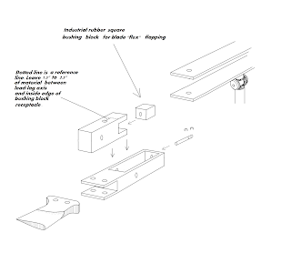


This video is the reason for my concern for not having flapping hinges for dealing with dissymmetry of lift. Not a Schoffmann helicopter.
Human Interface Rotor Systems and Morphing Airframes
I wanted to share a few words regarding my interest in HMI (Human Machine Interface). My goal is practical application, so if you're a dooms day follower...sorry I let you down. The human interface software that interests me is none invasive and the idea is to aid operation rather "turn it loose" on it's own and see what happens. Regarding my helicopter designs, for example, should a pilot pass out, the system would notice the unwanted changes in flight control input. I always want a "human in the loop". The only "invasive human interface I think would be ok is that regarding amputees or paralyzed people. They're doing wonderful work to that end and even National Geographic did an article on it.
This effort is not an attempt to replace any UAS. It is simply an update on my approach/effort to civil UAS and manned platforms. I am still not funded by the Army regarding my patent (Pat # 8,226,026 B2) nor is my endeavor to get the platform off of paper and into the air. But, I'm still going to keep "plugging" away on my own. The designs that I've given to the Army/DOD are separate. Further I have nothing to do with any military rotorcraft/aerospace programs outside of the designs that were given.
I finally made head way in getting the 2nd coaxial HIR prototype into the air with fairly good control for the first hop flight. No swash plate.
Some of you may be thinking it resembles the Japanese GEN H4 or the Airscooter coaxial systems, but those respective airframes, though innovative, are simply tilt mast and both airframes are fixed pitch. Now, my small scale coaxial is also fixed pitch, but it's not simply "tilt mast". It is two airframes that are interconnected with the upper airframe containing the rotor system, tilting independently from the lower airframe, thereby allowing for the application of full collective pitch and yet the weight remains equally distributed between both airframes. If the upper airframe tilts forward, the rotor thrust is vectored as well as the lower portion of the upper airframe that interconnects with the lower airframe via a longitudinal lever/airframe strut, moves aft, but at equal moments, "flexing" the CG rather than a lateral or linear shift in weight within the airframe. A sort of "pendulum" flex, if you will. My theory.
If you review the video clips of the GEN H4 flying, the operator appears to have a "cautious" hold on the control stick that tilts the power plants and masts, but it appears too "loose" as if it may be more easily to over correct, but I cannot be certain. It appears not to be intuitive. With "planform" morphing/HIR airframes, the control stick manipulates both airframes, but not in a "stick to the rotor discs" manner. Connecting the weight of both airframes together, to include the pilot weight in a manned platform, adjusts the the attitude of the upper airframe/masts for direction control. Should any atmospheric gusts hit the rotor discs, it will be translated into both airframes, pilot weight, and then to the control stick. That translation from the rotor discs is "buffered". Further, there may be better control feedback to the operator. With the GEN H4, an atmospheric gust would seem to translate straight to the control stick as the rotor masts/power plants ride on a single gimbal. My platform will use a gimbal as well, but there are always two attachment points between the two airframes with the control stick controlling movement between the two. The GEN H4 has one attachment point between the rotor discs and lower airframe. Two if you count the pilot's hand on the control stick. Now, I need to get the 1st single mast prototype flying. The airscooter again is fixed pitch. Further, it utilizes both a dif. gear system and a polychain pulley system.
Later this week, I will move outdoors and attempt maneuvering around obstacles. Last year, my original plan was to include some sort of "SMART" software that will assist in keeping the airframe in the most optimal configuration for translational flight. If you can remember learning to ride a bicycle and Mom or Dad kept their hand on the seat as you peddled away until you internalized the balance required and then they would let go of the seat. SMART software that can sense pilot control inputs and then make a decision of whether or not to adjust stick control input or take over. But, as of right now, my airframe is only a physical human interface regarding the weight of the pilot moving, interacting and assisting the airframe configuration in control of the platform/thrust vectoring during flight. Time will tell.
Outdoor Flight
I'm still not satisfied. Made some changes, 180 degree flip on the forward/aft servo, but no a cherping has developed, causing inconsistent rpms and excessive yaw that neither the trim tab or yaw control surface can counter. The concept works, so I'm scaling up to gas powered. I have a 54 cc chain saw engine and I intend to use a go pro camera.
Airframe hit the ground from 15 feet....airframe was more rugged than I had expected. The combination adhesive with carbon fiber gusset plates was a good choice on my part. The battery/yaw control platform broke free. It still flew, but lost forward/aft control which I expected. Regarding planform morphing airframes, if there are not 2 points of connection with the weight equally distributed between both airframes, allowing both airframes to move within "one another" the lower airframe will act like a clock pendulum. I suppose my theory proved right.


http://www.youtube.com/watch?v=PKixR_89BQg
Airframe hit the ground from 15 feet....airframe was more rugged than I had expected. The combination adhesive with carbon fiber gusset plates was a good choice on my part. The battery/yaw control platform broke free. It still flew, but lost forward/aft control which I expected. Regarding planform morphing airframes, if there are not 2 points of connection with the weight equally distributed between both airframes, allowing both airframes to move within "one another" the lower airframe will act like a clock pendulum. I suppose my theory proved right.


Airframe detail below
http://www.youtube.com/watch?v=PKixR_89BQg
Sunday, August 12, 2012
Finally got the 2nd prototype helicopter of my patent up and flying; no swashplate; planform morphing airframe rotor disc control. I still need to tweak the yaw control and increase the surface area of the yaw paddle. I added a small washer w/ some teflon grease between the reduction gears, but it may be causing a little friction, slowing one of the mast down and causing excessive yaw, but it can be negated with additional yaw control input to counter it. More tweaking and I can move outdoors now. Now to get the boom and pod single mast platform flying.
Friday, August 10, 2012
Coaxial Prototype of HIR
The 2nd coaxial prototype of my patent flew, but the CG is off. It drifts aft and to the left. Further I need to cut some weight on the airframe.http://www.youtube.com/watch?v=gzYRF9xLs9s
Sunday, July 15, 2012
Rotor Hub Review: Sikorsky S 34
Also known as the "H34 Choctaw" within military ranks, this helicopter has an interesting rotor hub assembly. Originally it had a large radial engine, but I have seen a few that have been brought to life and uses a turbine power plant. The lead/lag axis utilizes a heavy hinges with vertical trunnions. Usual lead/lag hinges that I've seen are at the blade root or some type of flex beam inside of a couple of torsion bars combining lead/lag with flapping as seen in the Twin Star. But, I'm not an expert. Just thought it was an interesting set up.


RC Helo Review: Air Recon
My Step daughter Amy, got me this Air Recon indoor helicopter for Father's Day, made by Propel RC. Though the small platform costs a few "bags of nickels", the pay off is what it has to offer and that would be digital video as well as still photos. The still photos are a bit blurred, but let's face it, it's mounted on something that flies. The digital video feed is surprisingly clear, though it does not have a sound feed. It's a smooth operating little rotorcraft with very responsive control though it does not have a swash plate. Froward/Aft pitch is controlled by the small horizontal tall rotor that applies vertical lift upwards and down. Yaw control is governed by changing the RPM of one of the rotor discs. It's also a rugged bird as I have crashed it a number of times over the 4th of July weekend. I did manage to break the tail rotor when it hit my wife's mini-blinds, separating one of the tiny wires, but I managed to replace the motor. Now for those who do not tinker on their own, I would suggest buying parts made for the air recon helo. I usually do my own thing and bought a similar motor from the local hobby store. I re-ran the wiring to the new motor, splicing the ends with a good "bread tie" twist and used an flexible adhesive to protect the exposed wire rather than soldering the ends. The draw back to my replacement motor is that is was a bit longer, though the voltage was ok. It did change the center of gravity causing the helo to drift aft a bit, but I leveled the CG out by gluing a small machine nut to the nose. It reduced the run time a bit, but I enjoy the tinkering and process of problem solving. Video and pics are stored on a removable micro SD card that can be removed and place in the flash drive adapter to down load to your PC. All of the above mentions hardware comes with the helo. Charging the helo can be done from the transmitter as well as a USB slave cable that enables you to charge the helo from your PC. Over all not a bad package. The only draw back.....it's IR signal and not radio, so it can only be flown indoors because the sun screws up the IR signals.
The other airframes are coming along, but electrical issues I found to be faulty manufacturing.


The other airframes are coming along, but electrical issues I found to be faulty manufacturing.


Monday, June 18, 2012
Brushless Motor Electrical Wiring
I got most of the wiring done on the brushless motor with regard to the soldering. Both speed controllers seem to be working well in tandem.....that's what happens when you mix different configurations. Started the coaxial HIR airframe, but I want to finish the single mast first. Both platforms utilize planform morphing for rotor disc control rather than compliance.
Friday, June 15, 2012
Rotor Hub Review
First off, the following rotor hub is the property of Boeing Aerospace. This post is simply a review of said hub that is only my perspective as I depict this hub in different configurations. There is no intent to reproduce said hub in an effort to "copy" or duplicate the design, so do not get your panties or skivvies in a bunch. I have considered machining this hub to see how it functions on a small scale helo, but it would not be for profit, just my "brain food" and something mechanical to further occupy my fancy.
The "low vibration hub" is an interesting rotor hub assembly and I found it some time ago while "nerding out" looking through rotorcraft patents during my patent process. It clearly has the advantage of utilizing an "under slung" configuration, but without the risk of mast bumping that can occur in teetering under slug hub assemblies as a result of over correction of cyclic control. The lower part of the hub is linked in to the opposite rotor hub, so when the advancing rotor blade flaps up, it causes the retreating blade to flap down, elimination dissymmetry of lift. The patent drawings below illustrate more detail. Further, I have added some text and arranged the hub into different configurations to include a coaxial set up, simply for clarity and speculative review and trouble shooting. Again it is not an attempt to "take" Boeing's design.


The "low vibration hub" is an interesting rotor hub assembly and I found it some time ago while "nerding out" looking through rotorcraft patents during my patent process. It clearly has the advantage of utilizing an "under slung" configuration, but without the risk of mast bumping that can occur in teetering under slug hub assemblies as a result of over correction of cyclic control. The lower part of the hub is linked in to the opposite rotor hub, so when the advancing rotor blade flaps up, it causes the retreating blade to flap down, elimination dissymmetry of lift. The patent drawings below illustrate more detail. Further, I have added some text and arranged the hub into different configurations to include a coaxial set up, simply for clarity and speculative review and trouble shooting. Again it is not an attempt to "take" Boeing's design.


Sunday, June 10, 2012
JM2G Split Mast Rotor System: Dealing with the Industry
I have a buddy, Joseph Moylan (Morris), that I keep in touch with from time to time, but life keeps both of us busy toiling away to get by. This post has to do with a rotor system that he and another peer designed and presented to industry, to include Sikorsky Helicopters, McDonnell Douglas Helicopter Systems(MDHS) also a subsidiary of Boeing Aerospace, and select individuals at Georgia Tech. Both he and his associate were dealt with in a "short handed manner". Even though they are small entity, would it not have been less expensive to license or buy their patent out right? When you consider the R&D process, re-tooling and die, and lastly the legal red tape wrap up, it would have been cheaper, but these big companies still use questionable methods because the inventors are "small entity". Regardless of their reasoning, it is still poor business etiquette and wrong. Independent inventors and free lancers, always use caution. Their design was protected with a patent. The first paragraph was written by myself for my previous web site, w/ Joe's permission. The last portion starting with" A MUST SEE" was what I had copied from Joe's former web site. This is their story.
Joseph Morris (Moylan) and Gerard G. Grass, US Patent # 5,740,987. The JM2G concept was presented to Sikorsky Helicopters & Boeing, who acquired McDonald Douglas Helicopter Systems (MDHS). Mr. Moylan & Mr. Grass were told by Sikorsky that they (Sikorsky) believed the rotor system would work. Time passed & tests were conducted & behold Sikorsky filed for a patent after "redesigning" the four fasteners that held the JM2G rotor system to the airframe. Mr Moylan & Mr. Gerard received nothing, but the "run around" & "speak to our legal dep". There is an article in the Patent regulations that gives contractors patent infringement rights if it is found to be needed for a government contract. That is something I'm certain the industry does not want known. At any rate, the filing date proves ownership of the design to Mr. Moylan & Mr. Gerard, but big industry can out spend & out wait small entities from the private sector. It would be more cost efficient if industry would license or out right buy the patent rights. Instead, they'll waste money & time trying to find a way around the designers. Most of us in the private sector understand about acquisition costs & we are reasonable. There are those of us who want to see the advancement of rotor wing flight. Another example is DARPA, who last year was willing to throw $90,000 "bones" to an academy/research organization to figure out a new design for something. Most of us would have asked for much less than that as a "one time" licensing fee had the BAA request been along the lines of lets say my patent, but I'm just using that as an example. I cannot remember what the BAA request was for, but you get the idea. I have 7 more rotor systems drawn up and 3 of the 7 are ready for the patent office, but maintenance fees start adding up. That's another way big industry can stick it to you. So, inventers beware. On the "flip side" the industry cannot prevent you from selling your idea to others in the industry. If any fuss should arise....lets go to court & see whose patent filing date is older. I'm still going to build my design. Hide & watch. A tech magazine posted an article with a split axial tilt mast rotor system....without permission from the inventors.
NO ONE IS SAYING THAT MDHS (BOEING) & SIKORSKY PRODUCE POOR AIRCRAFT, IT'S JUST THAT THEIR BUSINESS ETIQUETTE IS "OFF BEARING" AT TIMES. THEY NEED TO TREAT INDEPENDENTS IN A FAIR BUSINESS MANNER.
Every significant change in our Nation was brought about by someone who thought outside the norm. The ones who tinker in their basements and garages. Look at Bill Gates. You think the college he attended gave him his software design? Compare Samuel Langley & Wright Brothers. Langley had the big government money that ended up in a river. The Wrights tinkered in their bicycle shop. Take for granted a serious thinker who is mechanically inclined & see what
happens.
From Joe's former web site. Red texts are my interjections pending tracking down info. Posted with permission of Joe Moylan:
A MUST SEE. Redstone Arsenal.
Date of this publication 3-13-2000. Studies for proposed air vehicles, the interesting part is that they have several parameters for taking into account of mast tilt angles and mast tilt functions. The funny part is that if variable mast tilting is NOT unique to us, then why the studies in 2000? After we disclosed to GaTech, Sikorsky, MDHS?
ADS10CSP.pdf.......(Working on finding this PDF..patients..sorry.)
From Popular Mechanics March 1996

http://books.google.com/books?id=L2UEAAAAMBAJ&pg=PA21&lpg=PA21&dq=tech+update+march+1996+on+the+level+copter&source=bl&ots=QBZBiyjIRn&sig=1Cj9SzpPg6Nx_v4oBBTMyrMdrtQ&hl=en&sa=X&ei=vNJ-UNqDL4fO2AWtwYGADw&ved=0CB0Q6AEwAA#v=onepage&q=tech%20update%20march%201996%20on%20the%20level%20copter&f=false
And, we have an update for the carter guys. This image appears to be one of the latest with their concept and patent pending application/10/782353 of their mast tilt configuration.
Image here
Before we get started with all of this gizmo talk. Let me make 2 points very loud and clear. Our patent provides for 2 primary aspects.
1. Is to tilt a rotor assembly, either for a helicopter, gyrocopter, autogyro, etc. Totally independant of any transmissions or fuselages. That means we tilt a shaft with all of its connecting swashplates, rotor head, rotorblades, etc all as a unit, relative to a helicopter body.
2. Our Device constitutes a mounting structure. That mounting structure as laid out per Col 4, line 44, Col 5 line 8 in the Patent as also in the claim section. "a rotor disc control plate is constructed of material having sufficient strength and having dimensions sufficient to support the mass of the helicopter....".
Does this mean that we are limited to the use of slide rods? absolutely NOT. In fact, we now have designs for several entirely different configurations and different helicopter platforms.
Please see our US Patent. 5,740,987 The technology(patent) is available for licensing or sale.
What is the role of the USPTO?
The U.S. Patent and Trademark Office (USPTO) administers the patent and trademark laws as they relate to the granting of patents for utility inventions, designs and plants and the issuing of trademark registrations. The USPTO examines applications for patents to determine if the applicants are entitled to patents and grants the patents when they are so entitled. It examines applications for trademark registration to determine if the applicants are entitled to register their trademarks and issues trademark registrations. The USPTO publishes issued patents, approved trademark registrations and various publications concerning patents and trademarks; records assignments of patents and trademarks; and maintains search rooms and a national network of Patent and Trademark Depository Libraries for the use by the public to study issued patents, registered trademarks, and pending trademark applications and records relating to both patents and trademarks. It also supplies copies of records and other papers.
US Patent Classifications
Class 244.
Sub Class 17.25 Lifting rotor having lift direction varying means This subclass is indented under subclass 17.11. Gyroplanes in which the direction of lift of the impeller is variable, either by a cyclic pitch control of the impeller thereby tilting the virtual axis of the impeller or by tilting the real axis of the impeller.
SEE OR SEARCH CLASS:
416, Fluid Reaction Surfaces (i.e., Impellers), subclasses 98+ and 148 for impellers, per se, having a tiltable axis or cyclic pitch control. 17.27, Lifting rotor supports, e.g., pylons. This subclass is indented under subclass 17.11. Gyroplanes including means to position or support the rotating wing on the aircraft.
SEE OR SEARCH CLASS:
416, Fluid Reaction Surfaces (i.e., Impellers), subclasses 121 , 149+ and 246 for a shiftable or adjustable impeller support.
Now, with regard to the USPTO Classifications on Class 416/146R, what does that say to do?
SEE OR SEARCH CLASS:
60, Power Plants, subclasses 495+ for a motor operated by the buoyancy of a fluid or by the vertical component of tides or waves.
74, Machine Element or Mechanism, for the combination with a named impeller* which is recited as a nominal load, i.e., no detail of the impeller or its relationship with the gearing or transmission is recited.
244, Aeronautics, for the combination of impellers* and aircraft structure where more aircraft details are recited than is necessary to mount the impellers.
277, Seal for a Joint or Juncture, for the combination of a sealing means between relatively moving parts, one of which may be an impeller* shaft, where no specific details are recited of the impeller or other fluid reaction surface mounted on the shaft.
366, Agitating, appropriate subclasses for (1) the combination of an agitating impeller* and a confining means (e.g., mixing chamber, etc.), (2) the combination of an agitating impeller and means functionally related to confining means for a fluid being agitated (e.g., structure which scrapes chamber walls; support specialized for use in or on a mixing chamber or closure therefore feed or discharge means to point of agitation; etc.), or (3) am impeller per se which is disclosed solely for agitating viscous or particulate solids, such as dough or sand.
384, Bearings, for the combination of a broadly recited impeller* and a bearing element supporting the impeller shaft. The recitation of a "blade" impeller is considered to be a detail sufficient to exclude a claim from Class 384 and classify it in Class 416.
415, Rotary Kinetic Fluid Motors or Pumps, for a fluid reaction surface (impeller*) and a means for guiding a fluid to, around or from the surface. The relationship between Classes 415 and 416 is that of combination - subcombination respectively. However, patents in Class 415, subclass 182.1 and 208.1 through 232, which claim a nominally recited casing and particular runner structure have been cross referenced to Class 416. For a complete search of runner or impeller structure, other appropriate subclasses in Class 415 should be considered. A patent including claimed means for confining, guiding or directing the fluid to or from an impeller* will be classified in Class 415. A waterfall has been determined to be directed fluid and an impeller claimed in combination therewith is classified in Class 415.
So what happened here? Was the MDHS Application filed in such an obscure manner that the examiners had no choice but to classify it under 416? OR was the classification requested? Or is there another reason we dont know about?
Moving Onward.
The United States Patent and Trademark Office has even foreseen a potential problem with Drafting claims in a patent. Especially once you've shown someone your information and technical writings. Thus, it is especially easy to draft anything to avoid a RED FLAG. Take a look.
From - USPTO MPEP 2000 - 2001.5
Information of Privity and/or Materiality
MPEP2000
Under the rule, information is not material unless it comes within the definition of 37 CFR 1.56(b)(1) or (2). If information is not material, there is no duty to disclose the information to the Office. Thus, it is theoretically possible for applicants to draft claims and a specification to avoid a prima facie case of obviousness over a reference and then to be able to withhold the reference from the examiner. The Office believes that most applicants will wish to submit the information, however, even though they may not be required to do so, to strengthen the patent and avoid the risks of an incorrect judgment on their part on materiality or that it may be held that there was an intent to deceive the Office.
(Side Notes:)
Carter Copters is now starting to become a leading contender with mast tilting. Mast tilt technology works if you understand the physics involved.
Nov 25-2005
LET ME SHOW THE MAJORS, HOW THE LITTLE PEOPLE ARE ACTUALLY THE MOST HONEST I'VE SEEN TO DATE! (Information retreived from USPTO Public Database)
IDS Carter Copters#1
IDS Carter Copters#2
The Attorneys and Guys at Carter have done their jobs. They DISCLOSED to the PTO, that WILL be applicable and may have the possibility of being vital to the outcome of their Patent Application. For pro or con. Clearly, there is NO VIOLATION, of the duty of disclosure here on Carters Team. Although we can not say the same of MDHS/BOEING.
To track the status of the Carter Patent Application click here:
USPTO/Carter Application
And we've managed to be added to a blogger. MarkEarnest.net
(End Side notes:)
We seem to be finding the bread crumbs to the hand...So far we've managed to find their parts...the expandable bushing bolts...Here
Compare the release pins of theirs in patent Fig 3 to that one in the link above.
Also scroll to the bottom of this page to view a side by side photo of our patent designs.
McDonnell Douglas Helicopter Systems i.e. Boeing, used our proprietary information (A 4 armed rotor disc control plate) presented during a face to face meeting (read page 4 par 1 and page 8 par 1) and then 2 years later applied for a patent on their own "Removable Helicopter Mast".
(Which is in our original report to them during our face to face meeting)
which uses the same 4 armed mounting plate and disconnect pins. Simply put, they stole our Proprietary Information for their own greed by direct and deliberate FRAUD, then gave the standard "sorry wont work" routine to have us go away.
For a quick view to bypass the writings, click on the JM2G History and scroll to the bottom of the page for a side by side view.
The image below is of this sites log files...Note the Interesting IP and the terms Edit Data...is it not strange how this shows up on the patent comp's page? Also it is very targeted terms. The Patent Numbers of both patents are used. Something more strange is that this ip belongs to cyveillance.com
(Continuing)
The only problem is that their(MDHS/Boeing) mounting plate Is Our Property by US Patent. Which means, that regardless of their design, tilting or not, their mast base meets the claims in the US Patent we filed and therefor should have been DENIED.
Some however may state the following: 35 USC 101 Whoever invents or discovers any new and useful process, machine, manufacture, or composition of matter, or any new and useful improvement thereof, may obtain a patent therefor, subject to the conditions and requirements of this title
I would agree with this. However, this is referring to (to my understanding) "published" patents, in which, the PTO examiner would "reference" and "cite" to the prospective Patentee. OR the patentee would have searched for himself the prior art, thus making the referenced patent known to the examiner...Now, how can they claim an improvement upon our patent when there are no references made by the examiner or the patentee in this case? They dont!
Then, in order for a patent to be issued, the following must be met: 35 USC 102
A person shall be entitled to a patent UNLESS: -
(a) the invention was known or used by others in this country, or patented or described in a printed publication in this or a foreign country, before the invention thereof by the applicant for patent, or
(b)the invention was patented or described in a printed publication in this or a foreign country or in public use or on sale in this country, more than one year prior to the date of the application for patent in the United States, or
(c)he has abandoned the invention, or
(d)the invention was first patented or caused to be patented, or was the subject of an inventor's certificate, by the applicant or his legal representatives or assigns in a foreign country prior to the date of the application for patent in this country on an application for patent or inventor's certificate filed more than twelve months before the filing of the application in the United States, or ......
Thus, the invention was known by MDHS Two Years prior to their filing of an application before the PTO to belong to US.
Secondly, the Invention was Caused to be patented and in the hands of our Patent Attorney and Filed Dec 1 1995. They Filed Dec 1997.
Look at the Search Field Classes on each patent. (More is explained in the JM2G history link).
Sec. 103. - Conditions for patent ability; non-obvious subject matter 35 USC 103
(a) A patent may not be obtained though the invention is not identically disclosed or described as set forth in section 102 of this title, if the differences between the subject matter sought to be patented and the prior art are such that the subject matter "as a whole" would have been obvious at the time the invention was made to a person having ordinary skill in the art to which said subject matter pertains. Patent ability shall not be negatived by the manner in which the invention was made.
Then moving on to the office actions for processing applications and confidentiality, the following is useful:
Sec. 122. - Confidential status of applications; publication of patent applications
(a) Confidentiality. - 35 USC 122
Except as provided in subsection (b), applications for patents shall be kept in confidence by the Patent and Trademark Office and no information concerning the same given without authority of the applicant or owner unless necessary to carry out the provisions of an Act of Congress or in such special circumstances as may be determined by the Director.
(cont'd)
(B)
(i)
If an applicant makes a request upon filing, certifying that the invention disclosed in the application has not and will not be the subject of an application filed in another country, or under a multilateral international agreement, that requires publication of applications 18 months after filing, the application shall not be published as provided in paragraph (1).
This paragraph would have been important for the office(PTO) to reference our patent had we been published after the 18month time frame. This would have made OUR Patent available for view after 18 months in which it would have provided a means for MDHS to view. This 18 mo. time frame would have been June of 1997. 6 Months prior to MDHS Filing.
Since, however, no citings were made with regard to our patent it is conceivable that we were held under confidential status up to the date of issuance. This places the date of public notification of 4-21-1998.
Now, after noting the above, the next section is the "oath of applicant".
Sec. 115. - Oath of applicant
The applicant shall make an oath that he believes himself to be the original and first inventor of the process, machine, manufacture, or composition of matter, or improvement thereof, for which he solicits a patent; and shall state of what country he is a citizen........
It is odd at the very least, to know that an oath must be made on a Federal Document, in which, "one" must claim by signature to be the original and first inventor. But, 2 YEARS AFTER information was disclosed to them?
Care to hear of our theory? About how a different named individual than whom we met with managed to come up with an idea, have it go through legal and then filing the Application before the PTO and not once get shot down internally?
I'd ask that you folks pay attention to dates. There was an IFW Scan performed on the MDHS Patent Application 4 years prior to the service even being started by the PTO. How did this happen?
Our Property Description:
Both of the patented designs (JM2G's & MDHS's) areusing a 4 armed (mounting/Control)plate, with arms extending radially outward from the center...
The center has a center hole for the Main Rotor Mast to come up through..
The arms of the Mounting plate have arm tube bores
The plate(s) Are/is the primary structural attachment...on both patents.
In Both patents, regardless of any tiling, a focal point must be both created and maintained. By the nature of their(MDHS) design, which is even stated in their own patent claims that the centerlines of the arms perpendicularly intersects the mast centerline. We clearly stated this in our patent claims two years prior....and, that focal point must be maintained "irrespective" of any tilting...
MDHS Patent Claim #7: The helicopter mast recited in claim 6 wherein: said mast has an axial mast centerline: and said aligned pair center lines lie in a plane which intersects said mast center line at a PERPENDICULAR ANGLE.
Thus, a focal point is created and must be maintained irrespective of ANY tilt. A direct read on our claim 2 B..(I): maintaining a focal point irrespective of the tilting of the upper rotor shaft:
(I) the focal point being locatable at an intersection of the means for attachment to the means for translating rotational motion to rotational motion and the means for translating rotational motion to rotational motion.
Their "quick release" mechanism will not be so quick release if it were not using the same four (4) armed plate design that we presented two years prior would it? Therefore, it would be safe to say that without using our plate, their whole quick release design would seem to be out the window.
The beauty of the Patent Office is the right to prohibit anyone from Making, Using or Selling. Seems to me that both designs would not work worth a damn without the mounting plate.
If patent law comes down to the claims of the patent? And if you have already given someone your information and drawings, then they would be able to completely fashion an application that would not get flagged. However, we claimed the following: A "Rotor Disc Control Plate" comprising at least 3 arms, but the preferred method having 4 arms, a mast center hole and arm cylindrical arm tube bores, a means for attachment, 1,(E,(V)c))...the means for attachment to the means for translating rotational motion to rotational motion is located at a locus where the longitudinal axis of the arm tubes intersects the first vertical axis. (See anything wrong here)?
Control is also derived of a secure "primary" attachment mounting point is it not? Is this not exactly what they are using...?
So if you read our report, JM2G operation and then go through the pages you will see the same design that we presented to them.
Now, some have asked me about the Patent Office examination of them...well, Their design never referenced our patent, Period. And if it was examined, it was never flagged and their patent was never rejected. What is really "ODD" about that, is to look at their patents field of search...244/17.27...compare that with our patent class of 244/17.25 and 244/17.27...Under normal conditions, we should have been a major red flag to them...We were never referenced. PTO problems?
They're using OUR 4 armed rotor disc control plate, as a quick release mount for the rapid removal of storage and shipping, of which by the way, the Government was soliciting contracts during the early 90's for rapid stevedore systems...
Now! our design when originally presented to MDHS/Boeing, was also a quick release design by pins. Once again, go read our report, its ALL IN THERE. Just a thought. Also, their quick release mount? Does it not seem the least bit strange to you that our system being removed and re installed in less than an hour would be a "quick release" system?
Now then:
The information on this site is to show the following four things:
1.) US Patent Information that belongs to the individuals, Gerard Grass and Joseph Moylan: And that they were the first to invent.
2.) That McDonnell Douglas Helicopter Systems, i.e. BOEING, Had (in our opinion)Stolen our private/secret information from us.
3.) To answer the questions that some investors have asked us.."why don't you take this to the big companies"? hahaaah...look around.
4.) To Answer the question "if this is so good, why is no one else doing it."? please see question #3.
This information is only show a record.
Aero article
The Sleazy B?
Mismanagement - Osprey this technology goes back to the 50's and they still cant get it to work. Many have asked how many men will die due to corporate greed when the politicians want the program dead...I'd have to agree with them.
The more Proof the better. Here it is The Lockheed Docs.
Boeing/Lockheed Docs
Go Take a Look at POGO. That is the Project on Government Oversight. at POGO and do a search for BOEING. if you find nothing there, then take a look at this file. Federal Contractor Misconduct Database 7 pages all on Boeing.
The link below is back because a few have requested it.
There's a long history on Boeing:
Boeing Engineer that's been screwed?
Boeingsux.com
Do a search on this one for Boeing, good information.
Ripoffreport.com
<AHREF="HTTP: content b3861044.htm? 03_49 magazine www.businessweek.comBoeinggate?
So rather than try to steal it? Why not just license or purchase it outright? Then they can have two patents and really go to town with the industry.
Joe's sketches:


Subscribe to:
Posts (Atom)